
Conveyor Timing Screws
Space and present bottles for the next machine operation with a bottle feed screw matched to the container and line. Define bottle geometry, pitch progression, rotation, equipment interfaces and speed before approving the design.
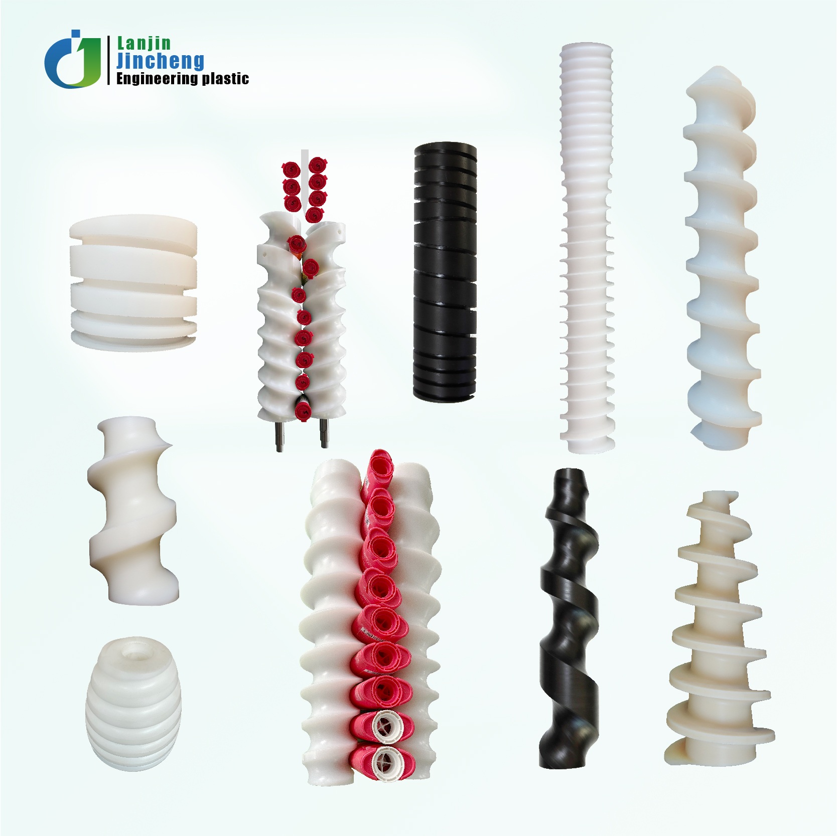
Start with the bottle and the production line.
| Required purchase information | What to supply | What is confirmed before production |
|---|---|---|
| Bottle geometry | Container drawing or samples, contact profile, height, dimensions and filled/empty condition | Groove/contact geometry, orientation and guiding arrangement |
| Pitch | Entry conditions, required exit center-to-center spacing and downstream machine reference | Constant/variable pitch profile, working length and transfer position |
| Rotation | Clockwise/counterclockwise from a named viewing end; bottle travel direction | Helix hand, rotation and machine-side layout shown on drawing |
| Equipment interface | Shaft ends, drive coupling, bearings, fixing, center height and adjacent components | Mounting dimensions and exact supply scope |
| Speed | Minimum/normal/maximum bottles per minute, belt speed and available screw RPM | Motion relationship, synchronization and validation conditions |
Match the screw to the actual bottle.
Round Bottles
Provide body diameter, height, neck/shoulder transition and contact-band location. Include container tolerances and filled weight.
Square, Oval & Shaped Bottles
Provide the complete profile, corner radii, desired orientation and permitted contact surfaces. Identify handles, seams, labels or easily marked areas.
Samples & Format Families
Supply representative samples and dimensional limits for each bottle format. Shared tooling across sizes requires feasibility review.
Empty and filled containers can behave differently. Include material, rigidity, weight, center-of-gravity concerns and any cap or closure present during conveying.
Define entry capture and exit spacing separately.
Entry & Pitch Progression
Describe how bottles reach the screw: accumulated, already spaced or transferred by another device. Provide entry orientation, guide arrangement and conveyor direction.
For variable-pitch duty, the pitch progression and acceleration profile must be reviewed with the bottle behavior and operating speed.
Exit & Downstream Handover
Specify bottle center-to-center spacing at the exit and the matching star wheel, filling, labeling or other downstream operation.
Include transfer centerlines, clearances and timing references. A single pitch number does not define the complete screw.
Overall length, working length, outside envelope, contact/groove profile, entry and exit geometry, pitch schedule where known, and transfer reference position. Agree all critical dimensions on an approved drawing.
Rotation direction needs a viewing reference.
| Direction detail | Required definition |
|---|---|
| Viewing end | Name the drive end or opposite end and show the observation direction on the layout |
| Screw rotation | Mark CW or CCW as seen from that defined end |
| Bottle movement | Show an arrow for the direction of travel and entry/exit positions |
| Machine side | Show where the screw and guide plate sit relative to the conveyor and bottle path |
| Helix hand | Confirm alongside rotation and travel direction on the final drawing; do not treat helix hand and rotation as the same specification |
Define what connects to the machine.
Shaft & Drive Connection
Provide shaft diameters, steps, lengths, keyways, flats, threads, coupling details and fixing method. Include fit tolerances and axial locating faces.
Mounting & Adjacent Parts
Show bearing/support positions, screw center height, belt elevation, guide plate and star-wheel interface. Identify the available installation envelope.
Parts Included
Specify plastic screw only, screw plus matching shaft, or other agreed components. Drives, bearings, sensors, guards and installation services are not assumed included.
Bottles per minute is not the same as screw RPM.
| Speed information | What to provide | Why it matters |
|---|---|---|
| Production rate | Minimum, normal and maximum bottles/min for each format | Defines the intended duty and validation range |
| Conveyor speed | Belt/chain linear speed with units and control behavior | Relates incoming bottle flow to capture and sliding contact |
| Screw rotation | Available RPM range, drive ratio and number of starts if known | Needed for the actual feed relationship; no universal one-bottle-per-revolution rule |
| Machine synchronization | Star-wheel reference, servo/electronic cam or mechanical timing details | Defines phase and transfer requirements |
| Operating behavior | Start/stop, acceleration, accumulation, format changes and duty cycle | Supports review of bottle stability and transition behavior |
No universal maximum speed is stated. Acceptance speed and trial conditions must identify the bottle format, bottle condition, guides, drive and downstream handover.
Specify the handling task and operating environment.
Spacing / Metering
Separate incoming bottles and present them at an agreed exit spacing for filling, labeling or washing equipment.
Grouping / Orientation
Grouping, bottle turning and lane-change tasks require a separate motion and layout review. State the exact input and output sequence.
Material Options
Our existing screw range lists UHMWPE, nylon, POM and PTFE. Confirm the grade using contact, cleaning, temperature, load and dimensional requirements.
Food-contact requirements need documentation for the exact grade supplied.
From bottle sample to approved machining brief
Container
Send bottle drawing, samples and format details.
Layout
Define pitch, rotation and machine interfaces.
Motion
Review speed range and synchronization.
Approval
Agree drawing, material and supply scope.
Order
Confirm quantity, sample, lead time and trial criteria.
Conveyor Timing Screws FAQ
Can you make a bottle feed screw from a sample?
A sample can support machining review. Bottle geometry, machine interfaces, direction, pitch and operating speed are still needed. Approve the final drawing before manufacture.
What pitch information is required?
Provide entry conditions, exit bottle center spacing, working length and downstream transfer geometry. For variable-pitch duty, confirm the complete progression or request a feasibility review.
How should I describe the rotation direction?
State CW or CCW viewed from a named end and show bottle travel direction. Confirm the helix hand separately on the layout.
Can you guarantee a particular bottles-per-minute rate?
Performance must be agreed for the specific bottle, machine layout, drive, guide system and test conditions. A throughput number alone is insufficient for confirmation.
Does the quotation include the shaft and drive?
Only the components explicitly listed in the offer are included. Identify plastic screw only or screw plus shaft, and confirm all additional parts separately.
What should I send for a quotation?
Bottle drawing or samples, pitch requirements, rotation reference, equipment interface drawing, speed range, material, quantity, destination and validation requirements.
Send the bottle and machine details.
Include bottle geometry, pitch, rotation direction, equipment interfaces and speed. Add the drawing revision, material, quantity and delivery destination.
Request a Timing Screw Quote
Bottle · pitch · rotation · interfaces · speed